Creo Parametric, the powerhouse CAD software, isn’t just about drawing pretty pictures; it’s about bringing engineering designs to life. From its humble beginnings to its current industry dominance, Creo Parametric has consistently pushed the boundaries of what’s possible in 3D modeling. This guide will walk you through its core functionalities, advanced features, and even some cool tricks you might not have known about, making you a Creo Parametric pro in no time.
Table of Contents
We’ll explore everything from basic modeling techniques to advanced simulations, covering its applications across various industries, like automotive and aerospace. We’ll also tackle troubleshooting, best practices, and even compare it to other CAD heavyweights. Get ready to level up your CAD game!
Introduction to Creo Parametric

Creo Parametric is a powerful 3D CAD software package used extensively in product design and manufacturing. It allows engineers and designers to create, analyze, and manage complex 3D models, ultimately streamlining the entire product development process. Its comprehensive suite of tools caters to a wide range of industries and applications, from aerospace and automotive to medical devices and consumer goods.Creo Parametric’s core functionality revolves around creating and manipulating 3D models.
This includes a broad range of modeling techniques, such as parametric modeling (allowing for easy modification of design parameters), direct modeling (providing flexibility for quick design changes), and surface modeling (for creating complex shapes and aesthetics). Beyond modeling, the software incorporates robust simulation and analysis tools, enabling users to evaluate design performance and identify potential issues before physical prototyping.
Furthermore, it offers advanced capabilities for data management, collaboration, and manufacturing preparation.
Creo Parametric’s History and Evolution
Creo Parametric’s lineage traces back to Pro/ENGINEER, a pioneering CAD software released in 1988 by Parametric Technology Corporation (PTC). Over the years, it has undergone significant development, incorporating new technologies and features to remain at the forefront of the CAD industry. Key milestones include the shift to a more intuitive user interface, the integration of advanced simulation capabilities, and the introduction of cloud-based collaboration tools.
The name changed to Creo Parametric in 2010, reflecting a broader product strategy from PTC. The continuous evolution of Creo Parametric is driven by the ever-changing needs of the engineering and design community, with regular updates and new releases introducing enhancements in performance, functionality, and user experience. For example, recent updates have focused on improving integration with other PTC software, such as Windchill and ThingWorx, to create a more holistic product lifecycle management (PLM) solution.
Target User Base for Creo Parametric
Creo Parametric is designed for a broad range of users involved in product development, from individual designers to large engineering teams. The primary user base includes mechanical engineers, industrial designers, manufacturing engineers, and product designers. The software’s versatility makes it suitable for various industries, including automotive, aerospace, consumer goods, medical devices, and machinery. Within these industries, users range from those focusing on conceptual design to those involved in detailed engineering and manufacturing planning.
The software’s advanced features and capabilities also make it a popular choice for experienced CAD professionals seeking a comprehensive and powerful tool. The learning curve can be steep, but PTC provides extensive training resources and support to help users of all skill levels master the software.
Creo Parametric Modeling Techniques
Creo Parametric offers a robust suite of modeling techniques, each with its strengths and weaknesses depending on the design complexity and desired outcome. Understanding these differences is key to efficient and effective CAD modeling. We’ll explore the core techniques and then dive into building a complex assembly.
Creo Parametric primarily utilizes two fundamental modeling approaches: feature-based modeling and direct modeling. Feature-based modeling, the more common approach, builds a part by adding features sequentially, like extrudes, revolves, and cuts. Each feature is defined by parameters, allowing for easy modification and design iteration. Direct modeling, conversely, allows for more intuitive manipulation of the geometry directly, often used for quick prototyping or modifying existing designs.
While feature-based modeling excels in managing complex designs and maintaining design intent, direct modeling offers flexibility for quick changes, but can be less manageable for large, intricate assemblies.
Feature-Based Modeling: A Detailed Look
Feature-based modeling is the workhorse of Creo Parametric. It’s a powerful approach where you build a part by adding or subtracting features, each defined by parameters. These parameters control the size, shape, and location of the feature, allowing for easy modification later. For example, you might start with a base extrude, then add a hole feature, followed by a fillet.
Changing the diameter parameter of the hole automatically updates the entire model. This parametric approach is crucial for design iteration and managing complex designs.
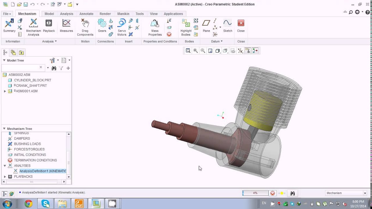
Creating a Complex Assembly: Step-by-Step Guide
Let’s build a simple but illustrative assembly: a gear assembly consisting of a gear, shaft, and housing.
- Create Individual Parts: First, create each component (gear, shaft, and housing) as separate parts using feature-based modeling. For the gear, utilize the “Gear” feature in Creo Parametric. The shaft is a simple extrude, and the housing could be created using extrudes, revolves, and cuts to achieve the desired shape with features for mounting the shaft and gear.
- Create the Assembly: Open a new assembly file. Insert each part into the assembly. Use constraints to define the relationships between parts. For instance, constrain the shaft to be concentric with the gear’s central axis and position the gear within the housing using appropriate constraints like mate constraints.
- Add Constraints: Precisely define the relationship between the parts using constraints like “mate,” “fix,” and “insert.” These constraints ensure the parts move and interact as expected within the assembly. Over-constraining can lead to errors, while under-constraining can lead to instability. The goal is to define just enough constraints to ensure proper assembly behavior.
- Validate the Assembly: After adding constraints, perform a design check to verify the assembly is properly constrained and functions as intended. This step ensures no unexpected behavior occurs during simulation or later design stages.
- Manage Assembly Structure: For larger assemblies, organize components into sub-assemblies to improve design management. This modular approach simplifies design, modification, and assembly.
Parametric Feature Usage: An Example
Consider designing a simple rectangular block with a hole. Instead of defining fixed dimensions, use parameters. Let’s say we use parameters “length,” “width,” “height,” and “hole_diameter.” The extrude feature would be defined by “length,” “width,” and “height.” The hole feature would use “hole_diameter” and a location defined relative to the block’s edges. Now, changing “length” or “hole_diameter” automatically updates the model, maintaining design intent and simplifying iterative design.
This parametric control is fundamental to Creo Parametric’s power and efficiency.
Advanced Features of Creo Parametric
Creo Parametric isn’t just for basic 3D modeling; it’s packed with powerful tools for advanced design and engineering analysis. This section dives into some of its most impressive capabilities, moving beyond the fundamentals to explore features that truly elevate the design process. We’ll look at simulation, design variation management, and software integration, showcasing how Creo Parametric streamlines complex workflows.
Simulation and Analysis Capabilities
Creo Parametric offers a suite of integrated simulation tools, allowing engineers to test and analyze designs virtually before physical prototyping. This reduces development time and costs while improving product reliability. These capabilities range from simple stress analysis to more complex simulations involving fluid dynamics and thermal behavior. For example, engineers designing a car engine block can use Creo Simulate to analyze stress distribution under various operating conditions, identifying potential weak points and optimizing the design for strength and durability.
The software provides visual feedback, displaying stress concentrations, displacements, and other critical data directly on the 3D model. This allows for iterative design refinement based on simulation results, leading to more robust and efficient products. Specific analysis types include Finite Element Analysis (FEA) for structural analysis, Computational Fluid Dynamics (CFD) for fluid flow simulations, and thermal analysis for heat transfer studies.
The results are presented in clear, understandable formats, making them accessible to engineers of varying experience levels.
Design Variation Management
Managing multiple design variations efficiently is crucial in product development. Creo Parametric provides robust tools to create and manage these variations systematically. This involves creating a “family table,” a spreadsheet-like interface where different design parameters are varied to generate multiple design instances. For instance, a company designing a line of smartphones might use a family table to manage variations in screen size, battery capacity, and internal memory.
Each row in the family table represents a unique design variation, and Creo Parametric automatically generates the corresponding 3D models based on the specified parameters. This eliminates the need to manually create each variation, significantly reducing design time and improving consistency across the product line. Furthermore, changes made to the base model automatically propagate to all variations, maintaining design integrity and reducing the risk of errors.
Integration with Other Engineering Software
Creo Parametric excels at interoperability, seamlessly integrating with other engineering software packages. This allows for a smooth workflow across different stages of the product development lifecycle. For example, Creo Parametric can exchange data with Computer-Aided Manufacturing (CAM) software for generating CNC machining instructions, ensuring a seamless transition from design to manufacturing. Similarly, it integrates with Product Lifecycle Management (PLM) systems, providing a central repository for managing design data, revisions, and collaboration across teams.
This collaborative approach reduces errors, improves communication, and streamlines the overall design process. The ability to import and export data in various formats, such as STEP, IGES, and JT, further enhances its compatibility with a wide range of engineering tools. This ensures data consistency and avoids the need for manual data translation, saving valuable time and resources.
Creo Parametric for Specific Industries
Creo Parametric, with its powerful modeling and simulation capabilities, is a go-to CAD software for a wide range of industries. Its flexibility allows for adaptation to the specific needs and challenges of each sector, leading to streamlined workflows and optimized product designs. This section will delve into how Creo Parametric is utilized in the automotive and aerospace sectors, and will offer a comparative overview of its application across various manufacturing fields.
Creo Parametric in the Automotive Industry
The automotive industry relies heavily on Creo Parametric for designing and manufacturing vehicles. From initial concept sketches to detailed engineering drawings and simulations, Creo Parametric plays a crucial role throughout the entire product lifecycle. Engineers use it to create complex 3D models of vehicle components, such as engines, transmissions, and body panels, ensuring precise fit and function. Advanced features like simulation tools allow for virtual testing of designs, identifying potential weaknesses and optimizing performance before physical prototyping.
For example, crash simulations help engineers design safer vehicles by predicting how the vehicle structure will react in a collision. Furthermore, Creo Parametric’s capabilities in surfacing and styling allow designers to create aesthetically pleasing and aerodynamic vehicle exteriors. The software’s collaboration tools facilitate seamless communication and data sharing among design teams, accelerating the development process.
Creo Parametric Applications in Aerospace Engineering
In the aerospace industry, where precision and safety are paramount, Creo Parametric is essential for designing aircraft, spacecraft, and their components. The software’s ability to handle complex geometries and intricate details is crucial for creating accurate models of aerodynamic surfaces, engine parts, and internal structures. For instance, engineers use Creo Parametric to design lightweight yet strong airframes, optimizing for both performance and fuel efficiency.
The software’s simulation tools allow for the analysis of stress, strain, and fluid dynamics, ensuring the structural integrity and aerodynamic performance of the design. Moreover, Creo Parametric facilitates the creation of detailed manufacturing drawings, essential for precise fabrication and assembly of aerospace components. A key example is the design of complex turbine blades for jet engines, where accurate modeling and simulation are critical for ensuring optimal performance and longevity.
Comparative Analysis of Creo Parametric Usage Across Manufacturing Sectors
Creo Parametric’s adaptability makes it suitable for diverse manufacturing sectors. While its application in automotive and aerospace is significant, its use extends to other industries as well. In the consumer goods sector, it’s used for designing electronics, appliances, and furniture. In the medical device industry, it’s employed for creating intricate models of implants and surgical tools. In heavy machinery, Creo Parametric aids in the design of complex mechanical systems.
The specific features utilized may vary depending on the industry. For example, the emphasis on surfacing and styling might be higher in the consumer goods sector, while the focus on structural analysis and simulation is more pronounced in aerospace and heavy machinery. However, across all sectors, Creo Parametric provides a common platform for design, collaboration, and manufacturing, improving efficiency and reducing time-to-market.
Creo Parametric User Interface and Workflow
Navigating the Creo Parametric interface and establishing a streamlined workflow are crucial for efficient design. Understanding the software’s layout and developing good habits from the start will significantly improve your productivity and the overall quality of your designs. This section will cover key aspects of the user interface and provide a suggested workflow for a typical project.
A well-defined workflow ensures consistency and minimizes errors. This is especially important in collaborative projects where multiple designers might be working on the same model. Proper file management is equally critical for avoiding confusion and data loss.
Creo Parametric User Interface Overview
The Creo Parametric interface is modular and customizable, allowing users to tailor it to their specific needs and preferences. The main window is generally divided into several key areas. The following table provides a visual representation of a typical layout. Note that the exact appearance may vary slightly depending on the version of Creo Parametric and the user’s customization settings.
| Area | Description | Typical Location | Functionality |
|---|---|---|---|
| Model Window | Displays the 3D model being worked on. | Center of the screen | Primary area for viewing and manipulating the model. |
| Model Tree | Hierarchical representation of the model’s components and features. | Usually on the left | Allows for easy selection and manipulation of individual parts and features. |
| FeatureManager Design Tree | Similar to the Model Tree, but organized by features. | Often alongside the Model Tree | Provides a feature-based view of the model’s creation history. |
| Toolbar | Contains frequently used commands and tools. | Top or bottom of the screen | Provides quick access to common functions. |
| Ribbon | Context-sensitive tabs offering tools related to the current task. | Typically at the top | Organized collections of related tools and commands. |
| Status Bar | Displays system information and current status. | Bottom of the screen | Provides feedback on current actions and system resources. |
Optimized Workflow for a Typical Creo Parametric Project
A typical Creo Parametric project might follow these steps:
A well-structured approach is essential for managing complexity and ensuring a smooth design process. This optimized workflow minimizes potential issues and promotes efficiency.
- Project Setup: Define project goals, create a new project directory, and establish a naming convention for files.
- Sketching: Create 2D sketches as the foundation for 3D features. Ensure sketches are well-constrained and dimensioned.
- Feature Creation: Build the 3D model by adding features (extrusions, revolves, cuts, etc.) sequentially. Use appropriate modeling techniques for efficiency.
- Assembly Modeling (if applicable): Assemble individual parts into a larger assembly, using constraints to define relationships between components.
- Validation: Conduct design reviews, perform simulations (FEA, CFD, etc.), and check for interference or other issues.
- Documentation: Create drawings, reports, and other documentation needed for manufacturing and communication.
- Revision Control: Implement a version control system (e.g., PDM) to track changes and manage different revisions of the design.
Importance of Proper File Management in Creo Parametric
Effective file management is paramount for avoiding data loss, confusion, and project delays. This includes:
Good file management practices are crucial for efficient collaboration and maintainability of your designs. This section Artikels the key aspects of effective file management within the Creo Parametric environment.
- Using a consistent and logical file naming convention (e.g., project name_part name_revision).
- Organizing files into folders based on project, part, and assembly.
- Regularly backing up project files to prevent data loss.
- Implementing a Product Data Management (PDM) system for larger projects to manage revisions and collaboration.
- Utilizing Creo Parametric’s built-in features for managing model versions and configurations.
Troubleshooting and Best Practices in Creo Parametric
So, you’re knee-deep in a Creo Parametric project, and things aren’t going exactly as planned. Don’t worry, it happens to the best of us! This section dives into common Creo Parametric pitfalls and how to avoid them, along with some killer tips for boosting your efficiency and keeping your projects organized.This section covers common errors, performance optimization, and data management strategies.
We’ll walk through solutions to frustrating problems and offer best practices to make your Creo Parametric experience smoother and more productive.
Common Creo Parametric Errors and Solutions
Let’s face it: errors are inevitable. Understanding common issues and their fixes is key to staying on track. Knowing what to expect and how to respond can save you hours of frustration. Here are a few examples:
- Model Corruption: This often occurs due to unexpected program closures or file system issues. The solution is to regularly save your work (frequently!), and consider using version control systems to track changes and revert to previous, stable versions if necessary. Also, ensure your computer meets the minimum system requirements for Creo Parametric.
- Geometric Errors: Over-constrained models, conflicting relationships, or incorrect dimensions can lead to frustrating geometric errors. Carefully review your constraints and dimensions; often, a visual inspection can reveal the problem. Using the Creo Parametric diagnostic tools can also help pinpoint the source of the issue.
- Assembly Issues: Problems assembling parts, such as interference or incorrect mating, are common. Check part orientations, component relationships, and use assembly constraints effectively. Breaking down complex assemblies into smaller, manageable sub-assemblies can greatly simplify the process.
Optimizing Creo Parametric Performance
A smoothly running Creo Parametric session is a happy session. Here’s how to keep things running smoothly:
- Hardware Considerations: Ensure your system meets or exceeds Creo’s recommended hardware specifications. Sufficient RAM and a powerful processor are crucial for handling large assemblies and complex models. A solid-state drive (SSD) significantly improves loading times.
- Model Simplification: For large assemblies, simplify your models where possible. Avoid unnecessary detail in areas not critical to the design. Use lightweight components or representations to reduce the computational load.
- Regular System Maintenance: Regularly clean up temporary files and defragment your hard drive (if using a traditional HDD). Keep your Creo Parametric installation updated with the latest patches and service packs. This can improve performance and stability.
Effective Data Management Strategies
Organized data equals a stress-free workflow. Effective data management is crucial for large projects or collaborative efforts.
Implementing a robust data management strategy is essential for large projects. This involves more than just saving your files; it encompasses a comprehensive approach to organizing, accessing, and sharing project data. This minimizes errors and improves collaboration.
- Version Control: Utilize a version control system (like Windchill or Git) to track changes, manage revisions, and collaborate effectively. This prevents overwriting work and allows for easy rollback to previous versions.
- File Naming Conventions: Establish a clear and consistent file naming convention. This allows for easy identification and organization of files within a project. A standardized approach helps maintain order and clarity.
- Project Folders: Organize your project data into clearly defined folders. This structure should reflect the project’s hierarchy, making it easy to locate specific files. Consider using a system of subfolders to further categorize data.
Learning Resources for Creo Parametric

So, you’re ready to dive deeper into Creo Parametric? Awesome! Mastering this powerful CAD software takes time and dedication, but the right resources can make the journey smoother. This section Artikels valuable learning paths and highlights often-missed features to supercharge your Creo skills.
Finding the right learning resources is crucial for efficiently mastering Creo Parametric. Many options exist, each catering to different learning styles and experience levels. Understanding these options and creating a structured learning plan is key to maximizing your time and effort.
Reputable Online Learning Resources
Several online platforms offer high-quality Creo Parametric tutorials and courses. These resources range from introductory materials for complete beginners to advanced training for experienced users. Choosing the right resource depends on your current skill level and specific learning goals.
- PTC University: PTC, the creators of Creo Parametric, offer official training courses covering various aspects of the software. These courses often include hands-on exercises and real-world examples, providing a comprehensive learning experience. They range from introductory courses for beginners to specialized training for advanced users in specific industries.
- YouTube Tutorials: Numerous YouTube channels provide free Creo Parametric tutorials, often focusing on specific techniques or features. While the quality can vary, many channels offer valuable insights and practical demonstrations. Be sure to check the channel’s reputation and the upload date to ensure the information is up-to-date and relevant to your version of Creo.
- Online Forums and Communities: Engaging with online communities dedicated to Creo Parametric can provide access to a wealth of knowledge and support. Users share tips, tricks, and solutions to common problems, fostering a collaborative learning environment. Platforms like PTC’s own forums or dedicated CAD forums on Reddit can be particularly helpful.
- Creo Parametric Help Documentation: PTC provides extensive help documentation directly within the Creo Parametric software. This is a valuable resource for finding detailed information on specific commands, features, and functionalities. While not a substitute for structured learning, it serves as an excellent reference tool for troubleshooting and clarifying specific aspects of the software.
Overlooked Features and Functionalities
Many new Creo Parametric users miss out on powerful features that can significantly improve their workflow and efficiency. Understanding these often-overlooked aspects is key to maximizing the software’s capabilities.
- Model-Based Definition (MBD): MBD allows you to directly associate manufacturing information with your 3D model, eliminating the need for separate drawings and reducing potential errors. This streamlined approach improves communication and collaboration between design and manufacturing teams.
- Simulation and Analysis Tools: Creo Parametric integrates simulation tools for stress analysis, motion simulation, and other engineering analyses. These tools enable designers to validate their designs early in the process, reducing the risk of costly errors and improving product performance.
- Customization and Automation: Creo Parametric offers extensive customization options through macros and scripting. These capabilities enable users to automate repetitive tasks, create custom tools, and tailor the software to their specific needs. This can significantly improve efficiency and productivity.
- Advanced Assembly Techniques: Techniques like component patterns, constraints, and relationships allow for efficient assembly modeling and management of complex assemblies. Mastering these improves the overall design process significantly.
Structured Learning Path for Beginners
A well-structured learning path is essential for effectively mastering Creo Parametric. This plan focuses on building a solid foundation before tackling more advanced concepts.
- Fundamentals: Begin with the basics – understanding the user interface, navigating the workspace, creating simple parts, and learning fundamental modeling techniques like extrude, revolve, and sweep.
- Intermediate Modeling: Once comfortable with the basics, progress to more complex modeling techniques, including using features like patterns, relations, and sketches to create intricate parts. Explore assembly creation and basic constraints.
- Advanced Modeling and Assemblies: Dive into advanced modeling techniques like surface modeling and freeform design. Master advanced assembly techniques, including component patterns, constraints, and managing large assemblies.
- Specialized Features: Explore specialized features based on your field of interest. This could include simulation, MBD, or specific industry-related tools.
- Practice and Projects: Consistent practice is crucial. Work on personal projects or participate in online challenges to solidify your skills and apply what you’ve learned.
Comparison with Competitor CAD Software
Choosing the right CAD software is a big deal, impacting everything from design efficiency to project costs. This section compares Creo Parametric with two major competitors, SolidWorks and Autodesk Inventor, focusing on features, usability, and licensing. Understanding these differences helps you make an informed decision based on your specific needs and budget.
Creo Parametric versus SolidWorks: Feature and Usability Comparison
SolidWorks and Creo Parametric are both powerful 3D CAD packages popular in various industries. However, they cater to slightly different user preferences and project requirements. SolidWorks is often praised for its intuitive interface, making it relatively easy to learn, especially for beginners. Its large user base also means ample online resources and community support are readily available. Creo Parametric, on the other hand, boasts more advanced features and a more robust set of tools for complex designs and simulations.
This power comes at the cost of a steeper learning curve. For example, SolidWorks’ assembly features might feel more streamlined for quick prototyping, while Creo Parametric’s advanced modeling capabilities excel in handling highly intricate and demanding projects. Ultimately, the “better” software depends on the user’s skill level and the project’s complexity.
Creo Parametric versus Autodesk Inventor: Advantages and Disadvantages
Autodesk Inventor and Creo Parametric both target professional engineers and designers, but they differ in their strengths. Inventor, integrated within the Autodesk ecosystem, benefits from seamless compatibility with other Autodesk products like AutoCAD and Revit. This interconnectedness is a major advantage for users already invested in the Autodesk workflow. However, some users find Inventor’s interface less intuitive than Creo Parametric’s, particularly in navigating complex assemblies.
Conversely, Creo Parametric’s strength lies in its powerful modeling capabilities and its focus on manufacturing processes. Its advanced simulation tools and direct modeling features can significantly streamline workflows for complex designs. A potential disadvantage of Creo Parametric is its higher learning curve and potentially higher cost of entry. The choice between them depends on the specific needs of the user and their existing software ecosystem.
Licensing Models of Creo Parametric and Competitor CAD Software
Licensing models for CAD software vary significantly, impacting both initial investment and ongoing costs. Creo Parametric typically employs a subscription-based model, offering varying levels of access to features and support. This model allows for flexible scaling of software access based on project needs. SolidWorks also offers subscription options, though perpetual licenses are also available. Autodesk Inventor predominantly uses a subscription model, similar to Creo Parametric, offering different tiers based on feature sets and support levels.
The best licensing model depends on budget constraints and the anticipated duration of software use. Perpetual licenses provide long-term ownership but lack the flexibility and automatic updates of subscription models. Subscription models offer regular updates and access to new features but involve ongoing costs.
Future Trends and Developments in Creo Parametric
Creo Parametric, already a powerhouse in the CAD world, shows no signs of slowing down. Its future hinges on integrating emerging technologies and anticipating the evolving needs of engineers across diverse industries. We can expect significant advancements driven by artificial intelligence, improved simulation capabilities, and a greater emphasis on collaboration and data management.
The next generation of Creo Parametric will likely see a blurring of lines between design, simulation, and manufacturing. This convergence will streamline workflows, reduce errors, and accelerate product development cycles. Imagine a system where design changes automatically trigger updated simulations, highlighting potential weaknesses or inefficiencies before prototyping even begins. This level of integration is not just a futuristic fantasy; it’s a realistic goal achievable through the strategic application of AI and machine learning.
Enhanced AI-Driven Design Assistance
AI will play a crucial role in boosting Creo Parametric’s capabilities. We can expect to see AI-powered features that offer intelligent design suggestions, predict potential design flaws, and automate repetitive tasks. For instance, imagine an AI assistant that suggests optimal material choices based on design parameters and performance requirements, or one that automatically generates multiple design variations based on user-defined constraints.
This level of automation would free engineers to focus on higher-level design decisions and problem-solving. Companies like Autodesk are already incorporating AI into their products, indicating a clear industry trend.
Advanced Simulation and Generative Design Integration
Creo Parametric’s future will involve deeper integration with advanced simulation tools. This will allow for more accurate and comprehensive analysis of designs, leading to improved product performance and reduced development costs. Generative design, already making inroads in other CAD platforms, will likely become a more prominent feature. This involves using algorithms to explore a vast design space and automatically generate multiple design options that meet specified criteria.
This could revolutionize the design process, especially for complex components with demanding performance requirements, such as those found in aerospace or automotive applications. Consider the example of designing a lightweight yet strong car chassis; generative design could explore thousands of possible configurations, optimizing for weight, strength, and manufacturing feasibility.
So, I’m totally swamped with this Creo Parametric project, rendering all these crazy parts. After I finish, though, I need to touch up some images for the presentation, so I’ll probably hit up gimp download to get the latest version. Then I can quickly edit my screenshots before I submit the whole shebang back to the professor.
Back to Creo Parametric – wish me luck!
Improved Collaboration and Data Management
Collaboration is key in modern product development. Future iterations of Creo Parametric will likely focus on enhancing collaboration features, allowing engineers in different locations to work seamlessly on the same design. This could involve improved cloud-based data management, real-time collaboration tools, and better integration with project management software. Improved data management will be crucial for managing the ever-increasing volume of design data.
This could involve the implementation of more robust data version control systems and improved search and retrieval capabilities. Think of a global engineering team working on a complex project; efficient data management is critical to prevent conflicts and ensure everyone is working with the latest version of the design.
Expanded Industry-Specific Solutions
Creo Parametric will continue to tailor its functionality to meet the specific needs of various industries. We can expect to see more specialized tools and features for sectors such as aerospace, automotive, medical devices, and consumer electronics. This will involve not just adding new features, but also optimizing existing workflows to align with the unique requirements and best practices of each industry.
For example, we might see enhancements to the software specifically tailored to the rigorous standards and complex geometries found in aerospace design.
Case Studies of Creo Parametric Applications
Creo Parametric’s versatility shines through in its real-world applications across diverse industries. This section will explore a specific example showcasing how its capabilities addressed a complex engineering challenge, ultimately improving product design and development. We’ll delve into the specifics, highlighting the software’s contribution to efficiency and innovation.
One compelling example involves the design and manufacturing of a high-performance electric bicycle frame. The engineering team at a startup, “CycleTech,” faced the challenge of creating a lightweight yet incredibly strong frame capable of withstanding significant stress during intense riding conditions. Traditional design methods proved time-consuming and lacked the precision needed to optimize the frame’s complex geometry for both weight reduction and structural integrity.
CycleTech’s Electric Bicycle Frame Design, Creo parametric
CycleTech leveraged Creo Parametric’s advanced modeling capabilities to overcome this hurdle. The team utilized parametric modeling to create a digital twin of the frame, allowing them to easily adjust dimensions and test various design iterations virtually. This iterative design process, enabled by Creo Parametric’s simulation tools, allowed CycleTech to analyze stress points, optimize material usage, and fine-tune the frame’s geometry for maximum strength-to-weight ratio.
The software’s ability to perform finite element analysis (FEA) was crucial in identifying areas prone to failure and making necessary design modifications before physical prototyping. This significantly reduced development time and costs associated with building and testing multiple physical prototypes.
Benefits of Creo Parametric in Bicycle Frame Design
The use of Creo Parametric yielded several significant benefits for CycleTech. First, the iterative design process facilitated by the software significantly reduced development time. What might have taken months using traditional methods was completed in a fraction of the time. Second, the precise simulations and analyses provided by Creo Parametric ensured the final design met the stringent strength and weight requirements.
This led to a superior product – a lighter, stronger, and more efficient electric bicycle frame. Third, the digital twin created in Creo Parametric facilitated seamless communication and collaboration among the design, engineering, and manufacturing teams. This streamlined the entire development process and minimized errors. Finally, the reduction in physical prototyping significantly lowered development costs, contributing to CycleTech’s overall profitability.
Creo Parametric’s Role in Reducing Development Time and Cost
The use of Creo Parametric’s simulation and analysis tools allowed CycleTech to identify and address potential design flaws early in the development process. This prevented costly rework and delays associated with physical prototyping and testing. The ability to virtually test and refine the design resulted in a significant reduction in both development time and cost. The precise control over design parameters enabled by parametric modeling also allowed CycleTech to explore a wider range of design options, ultimately leading to a more optimized and innovative product.
Customization and Extensions for Creo Parametric
Creo Parametric offers robust customization options, allowing users to tailor the software to their specific workflows and needs. This significantly boosts productivity and reduces the learning curve for individual users or teams working on specialized projects. By understanding the customization and extension capabilities, users can unlock the full potential of the software and create a truly personalized CAD experience.
Customizing the Creo Parametric interface and developing extensions involves a blend of built-in tools and external programming. The level of customization can range from simple changes like toolbar arrangement to the creation of entirely new functionalities through external applications. Understanding these options empowers users to streamline their design process and enhance their overall efficiency.
Interface Customization
Creo Parametric provides several methods for customizing the user interface. Users can modify toolbars by adding, removing, or rearranging frequently used tools. This allows for a more intuitive and efficient workflow, placing commonly accessed commands within easy reach. Additionally, users can personalize the appearance of the interface by adjusting colors, fonts, and other visual settings. This enhances readability and reduces eye strain during prolonged use.
The customization options are accessible through the application’s settings menu, which provides a straightforward and user-friendly interface for making these changes. A typical workflow might involve identifying frequently used tools, grouping them logically on a customized toolbar, and then adjusting color schemes for improved visual comfort.
Developing Extensions
Creating extensions for Creo Parametric usually involves programming using languages like C++ or VB.NET. These extensions can automate repetitive tasks, integrate with other software, or add entirely new features to the core application. The process typically begins with designing the extension’s functionality, followed by coding and debugging. Once complete, the extension is compiled and deployed within the Creo Parametric environment.
The development process requires a solid understanding of both programming and the Creo Parametric API (Application Programming Interface), which provides access to the software’s internal functions. For example, an extension might be developed to automatically generate reports based on design parameters, streamlining the documentation process. Another example could be an extension that integrates Creo Parametric with a specific manufacturing simulation software.
Third-Party Add-ons
A variety of third-party add-ons are available to enhance Creo Parametric’s functionality. These add-ons often address specific industry needs or provide specialized tools not included in the base software. They can range from simple utilities to complex plugins that integrate with other systems. The availability of these add-ons extends the software’s capabilities and offers solutions tailored to specific workflows.
Users should carefully research and evaluate add-ons before implementation, ensuring compatibility and suitability for their specific needs. For instance, a third-party add-on might offer advanced finite element analysis (FEA) capabilities or tools for improved data management and collaboration. The selection of an appropriate add-on depends on the specific requirements and priorities of the user or organization.
Last Word
So, there you have it – a whirlwind tour through the world of Creo Parametric. Whether you’re a seasoned engineer or just starting your CAD journey, we hope this overview has sparked your interest and equipped you with the knowledge to tackle any design challenge. Remember, practice makes perfect, so get out there, explore the software, and build something amazing! And hey, don’t be afraid to ask for help – the Creo community is vast and supportive.
Query Resolution
Is Creo Parametric difficult to learn?
It has a learning curve, but plenty of resources (tutorials, online courses) are available to help you master it. Start with the basics and gradually build your skills.
What kind of computer do I need to run Creo Parametric?
You’ll need a fairly powerful machine with a decent graphics card and plenty of RAM. Check PTC’s system requirements for the most up-to-date information.
Is there a free version of Creo Parametric?
No, Creo Parametric is a commercial software package. However, PTC offers free trials and student versions.
How much does Creo Parametric cost?
Pricing varies depending on the license type and features included. Contact PTC directly for a quote.
What file formats does Creo Parametric support?
It supports a wide range of formats, including its native .prt and .asm files, as well as common industry standards like STEP, IGES, and more.